Homemade wireless microphone circuit
1. Production instructions | |||||||||||||||||||||||||||||||||||||||||||||||||||||||||||||||||||||||||||||||||||||||||||||||
This FM microphone has the characteristics of stable frequency, easy production and ready installation. It is ideal for beginners with strong fun Sub-production. The microphone has high sensitivity, and can pick up the slight speech sound 3 meters away from the microphone; the effective transmission distance is 100 meters. | |||||||||||||||||||||||||||||||||||||||||||||||||||||||||||||||||||||||||||||||||||||||||||||||
| 2. Schematic diagram | |||||||||||||||||||||||||||||||||||||||||||||||||||||||||||||||||||||||||||||||||||||||||||||||
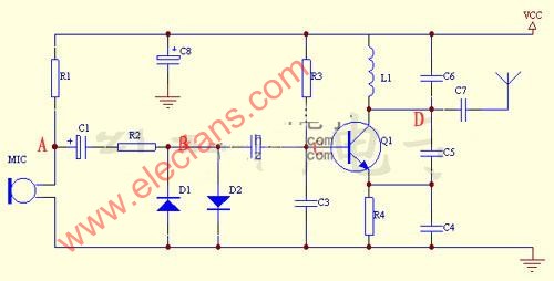 | |||||||||||||||||||||||||||||||||||||||||||||||||||||||||||||||||||||||||||||||||||||||||||||||
| 3. Simple circuit analysis | |||||||||||||||||||||||||||||||||||||||||||||||||||||||||||||||||||||||||||||||||||||||||||||||
C8 is the power supply bypass capacitor. R1 is the MIC offset to provide the microphone's static operating point. R1 MIC now constitutes the sound pickup circuit. C1 and C2 play the coupling role of sound signals. R2, D1, D2 make up the limiter circuit to prevent the microphone from input signal too large and serious distortion at close range. R3 and R4 are used to provide the static operating point of Q1. C3, C4, C5, C6, L1, Q1 constitute oscillation and amplification. C7 couples the signal to the antenna. The antenna emits the modulated sound signal. This circuit is powered by 3V, and two 1.5V batteries can be used. | |||||||||||||||||||||||||||||||||||||||||||||||||||||||||||||||||||||||||||||||||||||||||||||||
| 4. Commissioning | |||||||||||||||||||||||||||||||||||||||||||||||||||||||||||||||||||||||||||||||||||||||||||||||
A. If you purchase parts, you can measure while assembling, or you can measure once after all assembly. But you can get more fun while assembling. B. Connect the battery box to the PCB board, and then install the battery. A voltage of about 3V can be measured at VCC and ground. C. Install R1 and MIC. If you have an oscilloscope, you can measure a sine wave waveform of about 2mV by blowing the whistle at point A. The waveform fluctuates with your whistle. D. Install R3, Q1, R4, then use a multimeter to measure a voltage of about 1V at C, which determines the static operating point of Q1. E. Install C1, R2, C2, C3, C4, C5, C6, L1, C7 antennas. C7 can be replaced with a straight wire. After welding, you can observe a high-frequency oscillating wave at D with an oscilloscope. It does not matter if your oscilloscope can measure a low frequency. What you see is a cylindrical waveform. This proves that this circuit has started to work at this time. F. Turn on the radio and search in the FM band. When tuned to a place where the noise suddenly stops or howling, it means that the transmission frequency of this FM microphone is here. At this time, if you press L1 with your hand, you can feel that the transmission frequency has moved up or down. In other words, the transmission frequency can be changed by changing L1 (five-turn coil). Note that if the coil gap is too large or too small, the radio may not receive sound. G. To increase the receiving distance, you can lengthen or straighten the antenna. H. When all these are satisfied, finally connect D1 and D2. This allows the microphone to have a wider working range.
| |||||||||||||||||||||||||||||||||||||||||||||||||||||||||||||||||||||||||||||||||||||||||||||||
Electric Burner,Electrical Spiral Burner,Double Hotplate Burner,Single Hotplate Burner
Shaoxing Haoda Electrical Appliance Co.,Ltd , https://www.hotplates.nl