The antenna feeder system is an important part of microwave relay communication. The role of the antenna is to convert the electromagnetic waves transmitted in the feeder into electromagnetic waves transmitted in free space, or convert the electromagnetic waves transmitted in free space into electromagnetic waves transmitted in the feeder, and the feeder It is the transmission channel of electromagnetic waves. In the microwave relay communication circuit of the multi-channel shared antenna feeder system, the technical performance and quality indicators of the antenna feeder system directly affect the communication quality of the microwave channels of the shared antenna feeder system.
2 day feeder installation check:The antenna feeder system must be strictly in accordance with the specifications during installation and commissioning. There are concealed projects in the installation process of the antenna feeder system. Once the quality problems of the concealed project occur, it will leave hidden dangers for future maintenance. Therefore, the following aspects should be done. Installation inspection work:
(1) There should be no collision between the antenna and the feeder tower to prevent deformation and affect the technical performance.
(2) Check the height and orientation of the antenna installation according to the construction design drawings. The installation components should be tightened, otherwise the receiving level will be affected.
(3) The diameter of the microwave antenna is different. In order to better fix the microwave antenna, when the diameter of the microwave antenna is more than 3 m, especially in areas with high mountains, coastal areas and typhoons, it is best to use two horizontal rods and one vertical. The struts are used to secure the microwave antenna, and the fasteners that secure the tie rods and struts are larger than the contact faces of the tower.
(4) When the feeder is bent and twisted, the bending radius and the torsion angle should meet the requirements of the feeder manufacturer, otherwise the standing wave ratio of the feeder will be affected.
(5) When making the feeder flange, do not leave the broken copper chips in the feeder waveguide. Cut the feeder sheath with a wallpaper knife. The lower knife should not be too strong, so as to avoid scratches on the feeder, damage the feeder and affect communication.
(6) When the feeder is connected to the antenna, it must be naturally docked. Do not pull hard on the screw to avoid damage to the feeder or antenna feed for a long time. This part should pay special attention to prevent quality hazards.
(7) The antenna of the antenna feeder should be reliable and good. When the grounding device is connected to the galvanized parts of the tower, it must be tinned first. Each feeder must have three groundings. The position is behind the antenna, 1 m at the feeder, and the feeder is in front of the machine room. If the feeder length exceeds 30 m, the feeder is at the feeder. A grounding point should be added in the middle, otherwise the lightning will enter the equipment room along the antenna feeder and damage the equipment in the equipment room.
(8) The feeder should be firm and fixed once every 1.2 m to prevent the feeder from being damaged by the strong wind blowing and swinging for a long time.
3-day feeder debugging:(1) Antenna azimuth adjustment: The standard level is sent at the transmitting end. The digital microwave has a main antenna and a diversity antenna at the receiving end, and the main antenna is first adjusted, and the receiving level is repeatedly adjusted to meet the design requirements. After the main antenna is adjusted, fix the main antenna and adjust the diversity antenna so that the receiving level meets the design requirements, so that the antenna is adjusted.
(2) Standing wave ratio S: In the full frequency band, the standing wave ratio of the antenna feeder in the microwave rack should not be greater than 1. 15. If the requirements of the index are not met, check whether the joints of the antenna feeder are well matched and the bend radius of the feeder. And the angle of twist meets the requirements.
(3) Cross-polarization decoupling XPD: This index plays an important role in reducing cross-polarization interference in the same frequency and different polarization multiplexing. If the indicator fails in the test, the polarization direction of the two-station antenna feed can be adjusted.
(4) Feeder attenuation: The attenuation value of each feeder should not be higher than the design value. If it is unqualified, check whether the feeder is deformed by force or not, and the joint is well matched. If the ambient humidity is too large during construction, check the feeder for serious moisture condensation. If there is water in the feeder, it will increase the attenuation value and standing wave ratio of the feeder.
(5) Inflation pressure: The inflation pressure value is 13 kpa, and it is not lower than 11 kpa after 24 hours. Otherwise, it is necessary to check whether the antenna feeder seal is good and the inflator works normally. If the desiccant of the inflator becomes red, it must be replaced with desiccant. Otherwise, the purpose of drying the feeder can not be achieved, and the index of the feeder is affected.
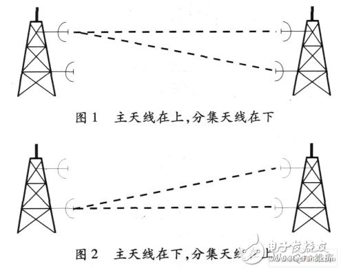
(6) The lengths of the two feeders connected to the main antenna and the diversity antenna respectively must meet the requirements of the delay, otherwise the reception quality will be affected. There are two main methods for digital microwave transmission. One is that the main antenna is on the top and the diversity antenna is on the bottom (see Figure 1). The other is that the main antenna is below and the diversity antenna is on (Figure 2).
When the main antenna is on the upper and the diversity antenna is below (as shown in Fig. 1), although the transmission signal in the diversity antenna has a larger space delay than the transmission signal in the main antenna, since the main antenna is higher than the diversity antenna, the feeder connected to the main antenna It is longer than the feeder connected to the diversity antenna, and is generally about 10 m long. Therefore, the delay of the two signals is not large, and the cable compensation is performed in the intermediate frequency portion.
When the primary antenna is at the bottom and the diversity antenna is on (as shown in Figure 2), the time delay of the transmitted signal in the diversity antenna is larger than that of the transmitted signal in the primary antenna. Since the diversity antenna is higher than the primary antenna, the feeder ratio of the diversity antenna is connected with The feeder connected to the main antenna is long, so the delay of the two signals is very large, and the cable in the intermediate frequency is compensated. In this case, the length of the feeder connected to the main antenna is lengthened to compensate the delay of the two signals.
Microwave antenna feeders are installed on outdoor towers. High-altitude winds cause mechanical vibrations to easily damage metal components. In addition, due to large temperature difference and high humidity, acid rain may occur in some places. Therefore, insulation materials and metals on the antenna feeder line. The aging of the material is fast, and the place where the antenna feeder is installed cannot be patrolled every day like the computer room. The failure of the antenna feeder is not easy to be discovered in time. In order to reduce the stand-off ratio of the off-site and the standing wave ratio of the antenna feeder, in addition to the selection of high-quality antenna feeder products, it is necessary to strengthen the maintenance of the antenna feeder system.
Usually, the screws of the antenna feeder system should be inspected. If the screws are loose, they should be reinforced in time. Especially before and after the typhoon is blown, be sure to pay attention to whether the screws are loose or not. In addition, it is necessary to pay attention to whether the antenna feeder system is deformed by force. If it is found to be deformed, it should be processed or replaced immediately. If the feeder is found to be damp, it should be dried in time.
5 day feeder system troubleshootingIn the microwave relay communication circuit of the multi-channel shared antenna feeder system, the antenna feeder system fault mainly has two characteristics: First, the same fault phenomenon occurs simultaneously in each channel of the shared antenna feeder system when the fault occurs; In the circuit, the failure of the feeder system is manifested by the decrease of the receiving level of each channel and the increase of the circuit noise. Common faults include: antenna azimuth offset, feeder collision deformation, poor sealing water inlet, and polarization decoupling.
In the maintenance, the fault can be judged according to the fault characteristics, and then the instrument test is used to analyze and determine the cause and location of the fault. When judging the antenna azimuth offset, do not rush to adjust the antenna, but determine whether the main antenna azimuth offset or the diversity antenna azimuth offset. If it is not the main antenna azimuth offset, the signal will not be interrupted, it may just be that the quality of the signal is a little worse. If the main antenna is removed, the signal will be interrupted. Therefore, do not move any components of the antenna feeder system when the fault point is not determined.
6-day feeder system monitoringWith the development of microwave communication to unattended, the network management system provides powerful monitoring and management for the equipment and circuit quality in the circuit, and provides monitoring functions for the antenna feeder system. Incorporating the antenna feeder system into monitoring and management will definitely improve maintenance efficiency and quality. According to the actual needs, two monitoring points are set in the antenna feeder system: one is the inflated part, which is easier to implement. The inflator has a remote signal interface, which can transmit the change of the inflation air pressure to the network management system; the second is the antenna orientation. In actual maintenance, this is also a part that is more prone to failure. It can detect the receiving level of each channel of the shared antenna feeder system, set the correspondence between the receiving level and the antenna position, and indirectly reflect the antenna position.
7 ConclusionPractice has shown that the planned inspection and maintenance of the antenna feeder system is the basis for reducing the failure of the antenna feeder system. The microwave stations can greatly reduce the off-air broadcast as long as they carefully organize the quarterly inspection and annual inspection of the antenna feeder system. Rate, do a safe broadcast.
Hdmi Cables,Hdmi Cord,Micro Hdmi Cable,Extra Long Hdmi Cable
UCOAX , https://www.ucoax.com