In this article, we continue to introduce a method for low-cost A/D conversion, but this method is cheaper and there is no need to use a comparator externally. The A/D conversion accuracy of this method is not high, only 6~7bit, and the measured voltage range is limited, but it is also very practical in some occasions where the accuracy requirement is not high and the measured voltage value does not change much. For example, temperature measurement.
Its circuit is shown in Figure 1:
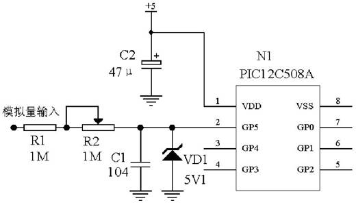
1, hardware description:
R1, R2 and C1 in Fig. 1 constitute an RC charging circuit, and are measured to charge C1 through R1, R2. N1 is a single-chip microcomputer, and the PIC12C508A of MICROCHIP is used in this circuit to illustrate. C2 is a filter circuit for power supply. VD1 is a Zener diode for protection to avoid damage to the microcontroller due to excessive input voltage.
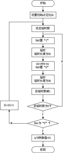
2, A / D conversion process:
First, GP5 outputs a low level, so that the power on the capacitor C1 is completely discharged, and then the GP5 is converted into an input state. At this time, the single chip starts timing, and the measured voltage is charged to the capacitor C1 through the R1 and R2 resistors, and the voltage on the capacitor C1. Will gradually increase, the voltage U on C1 satisfies the following formula:
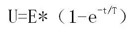
Where U is the voltage on capacitor C1, E is the input voltage (measured), T = (R1 + R2) * C1, and t is time.
When the voltage U on C1 reaches the gate voltage of the MCU I/O pin, the GP5 of the MCU changes from a low state to a high state. The time t elapsed from the start of charging to the time of the recording is recorded.
It can be seen from the above formula that when the gate voltage, R1, R2, and C1 values ​​of the I/O pin of the single chip are fixed, the measured voltage value E has a one-to-one correspondence with the time t.
Therefore, measuring the input voltage to charge the C1 capacitor to the gate voltage, and performing a table lookup calculation, the measured voltage value can be obtained, thereby realizing A/D conversion.
3, A / D conversion error analysis and solutions:
The error of A/D conversion is mainly determined by the following aspects, which are as follows:
(1) Power supply voltage VDD of the single-chip microcomputer: In the A/D conversion, when the VDD voltage changes greatly, the gate voltage of the I/O port may change, but the influence is small.
(2) The deviation of the internal timer of the MCU to the voltage rise time of the C1 capacitor: This measurement deviation is the main factor of the A/D conversion error.
(3) Error caused by unstable resistance and capacitance: When the value of resistor R1, R2 or capacitor C1 changes, the voltage of C1 capacitor will also rise to the gate voltage time, which will also affect A/D conversion. result.
(4) Input impedance of the I/O pin of the MCU: If the input impedance of the I/O pin of the MCU is low, it is equivalent to changing the RC value, which will also affect the A/D conversion result.
(5) The gate voltage of the single-chip microcomputer: For different single-chip microcomputers, the gate voltage may be slightly the same, which may also cause measurement error.
A/D conversion error solution:(1) The error caused by VDD can only be solved by increasing the accuracy of VDD voltage. The voltage of VDD is preferably stable within 2%, and the ordinary 7805 has 2% regulation accuracy.
(2) For the error generated by the internal timer of the microcontroller, the RC value can be increased, so that the voltage rise time on the C1 capacitor is prolonged, the value measured by the counter is larger, and the error is smaller. However, if the R value is too large, it will be affected by the input impedance of the I/O port.
(3) R1 and C1 are selected with high precision and stable resistance, capacitance, or a trimming resistor.
(4) If the input impedance of the I/O pin of the MCU is low, the resistance of R1 and R2 can be reduced, and the C1 capacitor can be added to solve.
4, A / D conversion speed and improvement methods:
Since the A/D conversion is obtained by charging a capacitor through a resistor through a resistor to make the voltage reach the gate voltage and then measuring the charging time to obtain the A/D conversion value, the A/D conversion speed is relatively slow, and it is suitable for In products that require less A/D conversion speed, the A/D conversion speed depends on the following aspects:
(1) RC value: When the RC value is too large, the measurement speed will be slower. Decreasing the RC value can increase the A/D conversion speed, but the measurement error will increase due to the shorter counting time.
(2) The magnitude of the measured voltage value: Since the voltage U on C1 is gradually increased from small to large, when the measured voltage value is small, the longer the U voltage rises to the gate embedded value, the completion of A/ The slower the conversion speed of D. On the contrary, the higher the measured voltage, the faster the measurement speed.
From the above, the speed of the A/D conversion can be increased by reducing the RC value. If the microcontroller has an external level shift interrupt, the accuracy of its A/D conversion can be improved.
5. Measurement range of input voltage:
The input voltage measurement range of A/D conversion is the power supply voltage (VDD) of the single-chip microcomputer gate voltage. If the voltage range to be measured needs to be increased, the input voltage can be measured by voltage divider, but its A/D conversion The error is affected by the voltage divider resistor.
6, A single-chip A / D conversion application examples:
The following figure shows an application example of implementing A/D conversion using PIC12C508. Four LEDs are used to indicate the corresponding voltage value range. Its voltage measurement range is from 1.4V to 2.55V with a measurement accuracy of 10mV.
For the application examples and the original program, refer to the MICROCHIP MCU application note, which can be downloaded from the MICROCHIP website.
The control switch is a special switch for process control of electrical control and thermal instrumentation. Specifically, there are positioning operation, self-resetting operation, positioning-self-resetting operation, blocking operation, positioning-blocking operation, self-resetting-positioning-locking operation and so on.
The types of control switches are:
ME Limit Switch
Micro Switch
QS5 Cam Switch
Universal Changeover Switch
Foot Switch
Proximity Switch (Sensors)
Switching Power Supply Unit
Float Switch
Weather Proof Isolating Switch
Isolating Switch and Changeover Switch
Control Switches,Float Switch,Proximity Switch,Cam Switch
Ningbo Bond Industrial Electric Co., Ltd. , https://www.bondelectro.com