Excessive routing delay can be caused by other factors besides congestion. The figure below shows another flow for reducing routing delay (processing flow where routing delay is too large due to other factors).
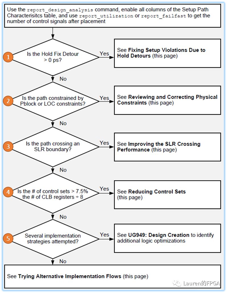
Image credit: page 7, ug1292
First, the path characteristics are analyzed by report_desigan_analysis. Sometimes it is necessary to combine the two commands report_utilization and report_failfast.
Step 1: Is the Hold Fix Detour of the analysis path greater than 0ps?
HoldFix Detour is the winding generated by the tool to fix the hold time violation (this value is displayed in the design analysis report, if it is not displayed, right-click in the report title bar and select HoldFix Detour). If this value is greater than 0, a setup time violation may occur. In this case, the focus should be on the hold time report corresponding to the path to diagnose why the tool repairs the hold time violation by routing.
Step 2: Are there location constraints for each logical unit of the violation path?
Often, some physical constraints, such as pin assignments, are unavoidable in a design. In addition to this, there may be other position constraints, such as those created via create_macro or Pblock. If the design changes, you need to be concerned about whether these location constraints are still reasonable, especially those paths that traverse multiple Pblocks.
Step 3: Does the violating path traverse the SLR?
If the target chip is a multi-die chip, the following factors should be considered at the early stage of design to improve design performance.
Insert pipeline registers at critical level boundaries of the design and on cross-die paths, especially cross-die paths, where these registers are required;
Check whether the resource utilization of each SLR is reasonable, which can be achieved by report_failfast --by_slr. The -by_slr option can only be used in the dcp generated by place_design or route_design, which is not difficult to understand, after all, the tool will place the design unit into the corresponding SLR in the layout stage;
The design of each die can be seen as a top layer, therefore, a die is assigned to each top layer to ensure that the corresponding design cells are correctly placed in the target die. This can be achieved through the attribute USER_SLR_ASSIGNMENT (supported since Vivado 2018.2);
If the above properties do not work correctly, you can directly draw Pblock for constraints;
If there are still timing violations after place or route, try using phys_opt_design -slr_crossing_opt.
Step 4: Is the unique control set percentage greater than 7.5%?
The number of unique control sets can be viewed through report_failfast. If the control set percentage exceeds 7.5%, the control set can be reduced as follows.
Pay attention to the MAX_FANOUT property:
Removes the MAX_FANOUT attribute for clock enable, set, or reset signals. This is because the property copies registers to reduce fanout, but also increases the control set;
During the Synthesis stage:
- Increasing the value of --control_set_opt_threshold allows the tool to move more synchronous control signals to the data path, thereby reducing the control set;
- Block Level Synthesis technology can also be used to set this value for the specified module;
In opt_design stage:
-control_set_merge
-merge_equivalent_drivers
These two options can help reduce the control set. But these two options cannot be used with -directive at the same time, so if it is in project mode, it can be placed in the Hook file (Tcl.pre or Tcl.post). In non-engineering mode, after executing -directive, execute these two options again;
Focus on low fanout signals:
For control signals with low fanout (synchronous enable, synchronous set/synchronous reset), the CONTROL_SET_REMAP attribute can be set to the connected register to move the control signal to the data path, thereby reducing the control set.
Step 5: Try Other Implementation Strategies
Vivado offers a variety of implementation strategies. Therefore, trying different implementation strategies is a means to achieve timing closure.
Try various place_design and phys_opt_design, this can be achieved by setting different -directive;
Try to use over-constraint (over about 0.5ns max), this can be achieved by setting Clock Uncertainty. Need to use set_clock_uncertainty;
Set a higher priority to the path under the key clock domain, so that the tool can prioritize its layout and routing, which can be achieved by the command group_path;
Try using incremental place and route, inheriting previous good place and route results, and reducing compile time.
Brushless Motor
Biotept Brushless DC motors have various advantages such as high efficiency, potential to downsize, ability to run on electric power, and low manufacturing costs. However, these motors have a number of disadvantages such as noise due to brush friction, generation of sparks and electrical noise, and limited life due to brush wear. Development of the Brushless DC Motor has solved all these problems.
We have several different style brushless motors
1, Y series frame brushless dc motor ofr industry machinery. The power from 0.55kw to 15kw. Frame size: 80, 90. 100. 112. 132
2, Circle Housing for Go Kart,Electric Scooter,Two Wheel Balance Scooter,E-Bike Electric Motorcycle,DIY Engine,Etc, 350W/500W/800W/1000W/1200W/1500W/1600W/1800W/2000W/2500W/3000W
Volt various from:24V/36V/48V
3. Custom some small size brushless motor. for general purpose

Brushless Motor,Brushless Dc Electric Motor,Brushless Ac Motor,Brushless Electric Motor,Planetary Gear Motor
Ningbo Biote Mechanical Electrical Co.,Ltd , https://www.biotept.com