The pulsed MIG welding can achieve droplet ejection transition and good axiality in a large current adjustment range. It is suitable for all-position welding, convenient and adjustable heat input, and good welding quality. It is widely used by domestic and foreign welding workers. s concern. Soft-switching technology uses resonant converter technology, which is characterized by the natural turn-on and turn-off of power devices under zero-voltage and zero-current conditions. It essentially overcomes the shortcomings of hard-switching arc welding power supplies, and to a large extent solves the problem of excessive power switch losses. According to the pulsed MIG process requirements, a soft switching pulsed MIG welding machine based on 80C196KC control was designed. The peak value, base value current adjustment range is 20~500 A, output no-load voltage is 70 V, the droplet transfer mode is jet drop transition, welding The parameters are independently adjustable.
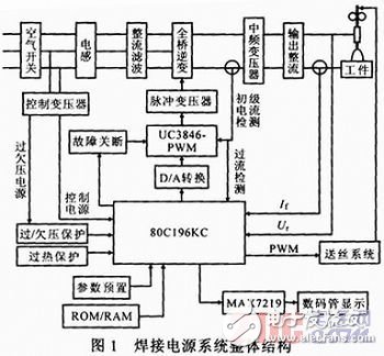
2 overall designThe overall structure of a soft switching pulsed MIG welding power system is shown in Fig. 1. It consists of three main parts: the main circuit, the control circuit, and the drive circuit. The system adopts the AC/DC/AC/DC inverter mode which is commonly used at present. The pulse switch signal is from the control instruction given by the single-chip microcomputer. After being driven and amplified, it provides a high-frequency pulse switch with a fixed frequency of 20 kHz for the power switch tube. signal. During the peak current, the peak current of the actual output is sampled. After A/D conversion, the peak current is sent to the MCU and compared with the given peak current. The MCU performs discrete PI calculation based on the deviation between the two and obtains one control parameter. The parameter adjusts the width of the high frequency control pulse of 20 kHz in real time so that the output peak current is equal to the given peak current. During the base value current, the same method is used to make the output base current equal to the given base current.
3.1 Main circuit working principle The main circuit structure of the full-bridge soft-switching inverter power supply is shown in Figure 2. It is divided into: anti common mode filtering, three-phase rectifier filtering, full-bridge inverter, power conversion and output rectification filtering. section.
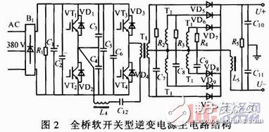
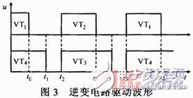
3.2 The working principle of the full-bridge soft switch The inverter circuit uses a soft-switching full-bridge inverter circuit, which consists of 4 IGBT switch tubes (VT1 to VT4), 4 anti-parallel diodes (VD1 to VD4 and an external IGBT absorption capacitor C3, C4 is composed of L4 as a resonant inductor and C12 as a blocking capacitor whose control principle is the same as the conventional phase-shift PWM control principle and is also PWM control over a wide range.The IGBT drive waveform is shown in Fig.3.
Before t0, VT1 and VT4 turn on the two IGBTs. At this time, current flows from A to B. At t0, VT1 is turned off in advance. At this time, capacitors C3 and C4 begin to charge and discharge. At this time, the pressure drop of VT2 decreases rapidly. Due to the small capacity of C3 and C4, in a very short time (before t2), the voltage drop of VT2 is reduced to zero, and the reverse conducting diode VD2 connected in parallel is turned on, and the current flow is C4→L4. → C12 → T1 → VT4, due to the decay of the primary current, the current flowing through VD2 also rapidly drops to zero, and the saturation inductance L4 blocks the reverse current from increasing, and at the same time, the voltage on the blocking capacitor C12 rises rapidly, keeping the primary current at zero. Therefore, at time t1, VT4 on the hysteresis arm is turned off in the zero current state; at time t2, VT2 is turned on in the state of zero voltage and zero current. Similarly, at time t3, VT2 is turned off in advance, and C3 and C4 start charging and discharging again. At this time, the current flow is VT3→T1→C12→L4→C4. In a very short period of time, C4 charging is completed, and the voltage and front end The positive voltage is equal. At this time, L4 blocks the current again in the opposite direction, blocking the capacitor from charging in the opposite direction, and generating high voltage in the opposite direction to prevent the primary current. Therefore, at time t4, the VT3 on the lagging arm is in the state of zero current. Shutdown; At t5, VT1 conducts at zero voltage and zero current.
In summary, the leading arm realizes zero current zero voltage switching (ZVZCS), and the lagging arm realizes zero current switching, so that the entire soft switching inverter circuit implements ZVZCS.
4.1 Working principle of the control system In the closed-loop control system of the single-chip microcomputer, the high-performance MCS-96 series single chip microcomputer 80C196KC is used as the core of the power supply control system, and the welding process control, current and voltage sampling, A/D conversion, PI operation and parameters are realized through programming. Presets and other functions. The whole system adopts closed-loop negative feedback control. The inverter adopts PWM method to control the output current. The control volume is sent to the pulse width modulation chip UC3846 via the D/A conversion circuit composed of MAX530, and the two PWM output signals with dead zone are output. After the IGBT is driven by the isolation of the pulse transformer, the characteristics of the output current are constant.
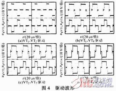
4.2 IGBT driving waveforms Figure 4 shows the measured IGBT driving waveforms. Figure 4a shows the driving waveforms ugVT1 and ugVT2 on the same bridge arm VT1 and VT2. It can be seen from the figure that the two driving waveforms have the same phase, the pulse width is equal, and they are expected. The same goal. Fig. 4b shows the driving waveforms ugVT1, ugVT4 on the same conduction loop VT1, VT4, ie, ugVT4 maintains the maximum pulse width, and the PWM adjustment is realized by controlling the pulse width of UGVT1. Figure 4c shows the drive waveforms ugVT2 and ugVT3 on VT2 and VT3. Figure 4d shows the drive waveforms ugVT3 and ugVT4 on VT3 and VT4. It can be seen from the figure that ugVT3 and ugVT4 always maintain the maximum pulse width, and only the pulse width of ugVT1 and ugVT2 changes according to the given value after PI calculation, and meets the requirements of the designed soft-switch main circuit.
The control system works under the control of the system software. The control program is the essence of the entire welding machine. The rationality of the structure, the practicality and reliability of the program become the key to the digital welding machine. A reasonable program structure and correct program flow are the basis for ensuring the normal work of the welding machine.
5.1 PI Control Algorithm The PI algorithm is one of the main tasks of the control software. The programming of the digital PID control algorithm is relatively simple. According to the specific requirements of the designed welding machine, combined with the previous research results, the system has proportions and integrals. The link can be satisfactorily controlled. Adding a derivative item can improve the dynamic quality of the system. However, its operation and parameter adjustment are more complicated, and it takes up too much time for the microcontroller to reduce the rapidity of the response. Therefore, the PI part of the PID algorithm is used here. Its control law is:
Where: α=K(1+T/TI), β=-K; ei, ei-1 are the difference between the current and feedback values ​​of the i-th and i-th currents, respectively; I(i), I(i-1) is the control parameter output to the MAX530 for the i-th and i-th-times respectively; the values ​​of α, β are determined by a large number of experiments.
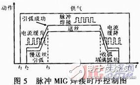
5.2 Welding process timing control According to the welding process requirements, the various processes in the welding process should be performed in sequence. Its timing control is shown in Figure 5.
5.3 Software anti-jamming measures Although the anti-jamming measures are taken in both the main circuit and the control circuit, the interference signal is only weakened to a certain extent and cannot be completely eliminated. Therefore, there will still be some interference that can invade into the SCM system. On the basis of hardware anti-jamming measures, we have consciously adopted several software anti-jamming measures: monitoring timers, redundant instructions, and digital filtering.
6 system debugging In order to verify the previously designed hardware circuits and software programs, the hardware and software programs need to be debugged in order to check whether they meet the design requirements. Analyze and improve various problems in the whole machine test to further improve the system design.
After passing the no-load test, the welder is subjected to a static load test. The welder output is connected to the load box, the panel given base value and peak current are the same, that is, the welder is in the constant current output state, the external characteristics of the welder are tested by changing the resistance value of the load box, and the external characteristic curve of the welder is drawn according to the test data. . Figure 6a is a welder output external characteristic curve determined at 65 A.
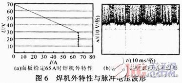
Figure 6b shows the pulse voltage waveforms for the manual welding of 5 mm thick Q235A carbon steel. The welding conditions were: wire diameter 1.2 mm, peak current 180 A, base current 50 A, duty cycle 30%, frequency 50 Hz, wire feed speed 4.5 m.min-1.
Welding under the above parameters, the process is stable, there is less spatter, the jet drop transition is achieved, the initial design goal is achieved, the weld seam is well formed and the penetration depth is large, and the 5 mm thick plate can be used for one-time penetration.
The main circuit of the welder adopts a soft-switching IGBT full-bridge inverter structure. Tests have shown that the hardware circuit has a reasonable structure, stable performance, zero current and zero voltage turn-on and shut-off, and a control system based on the 80C196KC single-chip microcomputer. And with a high degree of integration of a dedicated chip for control, in various aspects to take a variety of anti-interference and protection measures; the use of assembly language programming, software instructions, high efficiency, speed, and with software anti-jamming measures. Finally, a welding test was conducted. The test results verified that the design of the control system meets the requirements, a stable pulsed MIG welding is achieved, and the requirements of the pulsed MIG welding process can be met.
OTG USB Flash Drive is one serial of USB flash drive,which is hot selling right now and widely used on different mobiles,including Iphone and all smart phones which can support OTG function.More and more people choose it since it is quite small and very easy to take with.
There are mainly 4 kinds of OTG USB flash drive as below:
1. 2 IN 1 USB flash drive with micro(or Android)

2. 2 IN 1 USB flash drive with type C.

3.2 IN 1 USB flash drive with lighting for Iphone.

4.3 IN 1 OR 4 IN 1 USB flash drive with lightning/micro/USB C.


Most OTG USB flash drives start with 8GB until 256GB.You may also look for 1TB 2TB OTG USB memory stick but you will find the 1TB 2TB OTG USB flash drive you bought not working soon when you want to save more and more files,or even some files are missing.Why? Because they are not real full capacity!
We only do real full capacity as promised,and no upgrade or fake capacity from us.
otg usb flash drive, otg usb flash drive for apple iphone, best 3 in 1 usb flash drive,best type c usb flash drive,4 in 1 usb memory stick
Shenzhen Konchang Electronic Technology Co.,Ltd , https://www.konchangs.com