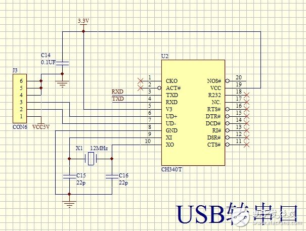
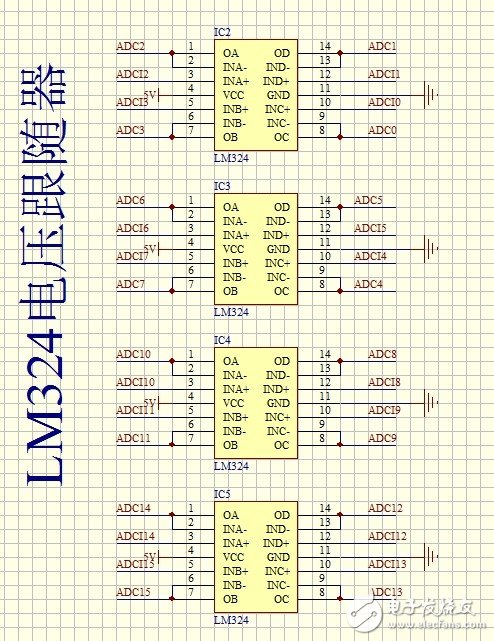
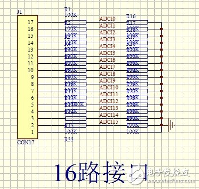
The following describes a 16-channel multi-channel ADC acquisition circuit diagram and source program made by STM32 microcontroller. The USB interface is used to connect with the computer, but the USB to serial port mode is used, so the host computer can use the serial port as the interface. The circuit diagram uses LM324 as a voltage follower to protect the pins of the microcontroller. Take the point directly on the computer USB, save the trouble of external power supply, the measured power consumption current is less than 20ma.
1. Main control circuit diagram: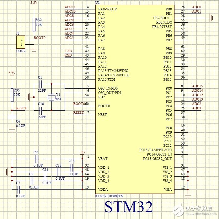
7.16 ADC initialization procedure:
voidAdc_Init(void)
{
/ / Initialize the IO port first
RCC-"APB2ENR|=0X7" "2; / / enable PORTA \ PORAB \ PORTC port clock
GPIOA-"CRL&=0X00000000;//PA01234567anolog input
GPIOB-》CRL&=0XFFFFFF00;//PB01anolog input
GPIOC-"CRL&=0XFF000000;//PC012345anolog input
//Channel 10/11 settings
RCC-"APB2ENR|=1" "9; / / ADC1 clock enable
RCC-"APB2RSTR|=1" "9; / / ADC1 reset
RCC-"APB2RSTR&=~(1""9);//Reset ends
RCC-"CFGR&=~(3""14);//divide factor clear
//SYSCLK/DIV2=12MADC clock is set to 12M, the maximum ADC clock cannot exceed 14M!
// Otherwise it will cause the ADC accuracy to drop!
RCC-"CFGR|=2" "14;
ADC1-"CR1&=0XF0FFFF; / / work mode is cleared
ADC1-"CR1|=0" "16; / / independent working mode
ADC1-"CR1&=~(1""8);//Non-scan mode
ADC1-"CR2&=~(1""1);//Single conversion mode
ADC1-"CR2&=~(7""17);
ADC1-"CR2|=7" "17; / / software control conversion
ADC1-"CR2|=1" "20; / / use external trigger (SWSTART)! ! ! Must be triggered with an event
ADC1-"CR2&=~(1""11";//Right Aligned ADC1-"SQR1&=~(0XF""20);
ADC1-"SQR1&=0" "20;//1 conversion in the rule sequence, that is, only conversion rule sequence 1
/ / Set the channel sampling time
ADC1-"SMPR2&=0X00000000;//Channel 0,1,2,3,4,5,6,7,8,9 sampling time clear
ADC1-"SMPR2|=7" "27; // channel 9239.5 cycles, increasing sampling time can improve accuracy
ADC1-"SMPR2|=7" "24; // channel 8239.5 cycles, increasing sampling time can improve accuracy
ADC1-"SMPR2|=7" "21; / / channel 7239.5 cycles, improve sampling time can improve accuracy
ADC1-"SMPR2|=7" "18; / / channel 6239.5 cycles, improve sampling time can improve accuracy
ADC1-"SMPR2|=7" "15; / / channel 5239.5 cycles, improve sampling time can improve accuracy
ADC1-"SMPR2|=7" "12; / / channel 4239.5 cycles, improve sampling time can improve accuracy
ADC1-"SMPR2|=7" "9; / / channel 3239.5 cycles, improve sampling time can improve accuracy
ADC1-"SMPR2|=7" "6; / / channel 2239.5 cycles, improve sampling time can improve accuracy
ADC1-"SMPR2|=7" "3; / / channel 1239.5 cycles, improve sampling time can improve accuracy
ADC1-"SMPR2|=7" "0; / / channel 0239.5 cycle, improve sampling time can improve accuracy
ADC1-"SMPR1&=0XFFFC0000;//Channel 10,11,12,13,14,15 sampling time clear
ADC1-"SMPR1|=7" "15; / / channel 15239.5 cycle, improve sampling time can improve accuracy
ADC1-"SMPR1|=7" "12; / / channel 14239.5 cycles, improve sampling time can improve accuracy
ADC1-"SMPR1|=7" "9; / / channel 13239.5 cycle, improve sampling time can improve accuracy
ADC1-"SMPR1|=7" "6; // channel 12239.5 cycles, increasing sampling time can improve accuracy
ADC1-"SMPR1|=7" "3; / / channel 11239.5 cycle, improve sampling time can improve accuracy
ADC1-"SMPR1|=7" "0; / / channel 10239.5 cycle, improve sampling time can improve accuracy
ADC1-"CR2|=1" "0; / / open AD converter
ADC1-"CR2|=1" "3; / / enable reset calibration
While(ADC1-"CR2&1" "3); / / wait for the end of calibration
//This bit is set by the software and cleared by hardware. This bit will be cleared after the calibration register is initialized.
ADC1-"CR2|=1" "2; / / open AD calibration
While(ADC1-"CR2&1" "2); / / wait for the end of calibration
//This bit is set by the software to start calibration and is cleared by hardware at the end of the calibration
}
8. The procedure for obtaining the ADC value:
/ / Get the ADC value
//ch: channel value 1~16
u16Get_Adc(u8ch)
{
U8ch_ch;
Switch(ch)
{
Case1:ch_ch=8;break;
Case2:ch_ch=9;break;
Case3:ch_ch=14;break;
Case4:ch_ch=15;break;
Case5:ch_ch=6;break;
Case6:ch_ch=7;break;
Case7:ch_ch=4;break;
Case8:ch_ch=5;break;
Case9:ch_ch=2;break;
Case10:ch_ch=3;break;
Case11:ch_ch=1;break;
Case12:ch_ch=0;break;
Case13:ch_ch=12;break;
Case14:ch_ch=13;break;
Case15:ch_ch=11;break;
Case16:ch_ch=10;break;
Default:ch_ch=88;break;
}
If(ch_ch==88)return0;
/ / Set the conversion sequence
ADC1-"SQR3&=0XFFFFFFE0;//Regular sequence 1 channel ch
ADC1-"SQR3|=ch_ch;
ADC1-"CR2|=1" "22; / / start rule conversion channel
While(!(ADC1-"SR&1" "1)); / / wait for the end of the conversion
returnADC1-"DR; / / return adc value
}
9. A function that converts the ADC value into a voltage value:
//ch range 1~16
Voidfetch_adc(u8ch)
{
U16adcx;
U32temp;
If((ch==0)||(ch)16))return;//If it is not 1 to 16, the channel is invalid, exit function
Adcx=Get_Adc(ch);// Get the ADC value
Temp=(u32)adcx*3300/4096;//calculate voltage value unit mv
Adcx=temp;//Get the calculated voltage value
Adc_buf[ch*2-2]=adcx》8;//Assign adc_buf, first assign 8 digits, then assign 8 digits lower
Adc_buf[ch*2-1]=adcx;
}
The biggest selling point of LCD monitors is their ever-improving response times, from the initial 25ms to the current 4ms grey scale. The response time determines the number of frames a monitor can display per second. Typically, when the screen is displayed at more than 25 frames per second, the human eye sees the rapidly changing images as continuous.
According to the size of points
LCD monitors are divided into: 3.5 -inch LCD monitor / 5.6 -inch LCD monitor / 8 inch LCD monitor / 10.4 inch LCD monitor / 12 inch LCD monitor / 15 inch LCD monitor / 17-inch LCD monitor / 19 inch LCD monitor / 20 inch LCD monitor / 22 inch LCD monitor / 24 inch LCD monitor / 26 inch LCD monitor / 32 inch LCD monitor / 37 inch LCD monitor / 40 inch LCD monitor / 42 inch LCD monitor / 46 inch LCD monitor / 47 inch LCD monitor / 52 inch LCD monitor / 55 inch LCD monitor / 65 inch LCD monitor / 70 inch LCD monitor /82 inch LCD monitor, etc. /84 inch LCD monitor /84 inch LCD monitor, 110 inch LCD monitor.
According to the color points
Color, black and white monitor. CRT monitors are classified by scanning mode: interlaced, progressive scanning, etc., while LCD monitors are not distinguished by scanning mode.
Frame Monitor,Open Frame Touch Screen,Open Frame Display,Open Frame Touch Monitor
Shenzhen Zhenniu Technology Co., Ltd , https://www.tydisplay.com