1 Introduction
Digital Signal Processor (DSP) is a kind of microprocessor suitable for digital signal processing and calculation, which can realize real-time and fast digital signal processing algorithm. Usually, a DSP-based core is equipped with peripheral functional circuits required for measurement and control, which are integrated into a single chip, which greatly reduces the price of the chip, reduces the size, has a compact structure, is convenient to use, and improves reliability. Therefore, the multi-function board with integrated DSP chip is an ideal choice for motor applications, excitation pulse control systems, and power protection systems. In this paper, the CS4U9813 programmable intelligent multi-function board of Supertop Industrial Control is used as the controller of the servo motor to realize the steering function of the rear wheel of the car. The board integrates the high-performance DSP chip TMS320F2812 of TI.
2 Structural characteristics of TMS320F2812 [1] [4]
TMS320F2812 is the most advanced and most powerful 32-bit fixed-point DSP chip currently launched by TI on the market. It has both digital signal processing capabilities, powerful event management capabilities and embedded control functions, and is particularly suitable for industrial automation, motors, and motor servo control systems. The TMS320F2812 chip structure uses a Harvard structure with improved program and data storage separated, 8-stage pipeline operation, 128-bit key protection, almost all instructions are completed in 6.67ns (150MHZ), up to 1MB of external memory interface, up to 56 An independent programmable, multi-purpose input / output (GPIO) pin is the best choice for implementing a motion control system. The functional block diagram is shown in Figure 1, and its main performance is as follows:
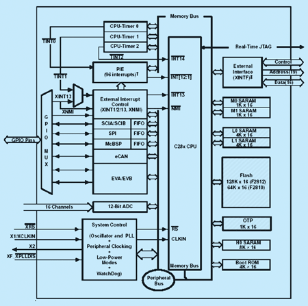
Figure 1 functional block diagram
(1) High-performance 32-bit central processing unit
l Main frequency 150MHZ (clock cycle 6.67ns), low power consumption (core low voltage 1.8V, I / O port 3.3V)
l 16-bit × 16-bit and 32-bit × 32-bit multiply and accumulate operation
l Unified register programming mode, linear program address and data address up to 4M words
(2) On-chip memory
l 8Kx16-bit Flash memory
l 1Kx16-bit OTP read-only memory
l L0 and L1: two 4Kx16-bit single-port random access memory (SARAM)
l One 8Kx16-bit single-port random access memory
l M0 and M1: two 1Kx16-bit single-port RAMs
(3) Clock and system control
l Support to dynamically change the frequency of PLL (PLL)
l On-chip oscillator
l Watchdog timer module
l CPU-level and peripheral-level interrupt combined control system
(4) Rich peripheral equipment
l Two event managers (EVA, EVB)
l Serial Peripheral Interface (SPI)
l Two serial communication interfaces (SCI), standard UART
l Improved Controller Area Network (ECAN)
l Multi-channel buffered serial interface (MCBSP)
l 16-channel 12-bit digital-to-analog converter (ADC)
3 Realization of four-wheel steering control system
Four-wheel steering (Four-Wheel Steering, referred to as 4WS) system refers to the vehicle in the steering process, the front and rear two groups of four wheels can function as needed, can effectively improve the vehicle's maneuvering flexibility and handling stability, is getting Continuous development and application. When the 4WS car is turning at a low speed, the front and rear wheels turn in reverse phase, which can reduce the turning radius of the vehicle. When turning at a high speed, the front and rear wheels mainly turn in the same phase, which can reduce the side angle of the vehicle's center of mass β and reduce the stability of the vehicle State overshoot, etc., to further improve vehicle handling stability.
The four-wheel steering platform constructed in this paper is composed of a DC servo motor with a worm gear reduction mechanism, an electromagnetic clutch and a common front wheel steering mechanism. Among them, the motor power supply is DC12V, the reduction ratio is set to 10: 1 (adjustable), and the electromagnetic clutch power supply is DC48V. The control strategy adopts a direct yaw rate closed-loop control combining feedforward and feedback, in which the front wheel rotation angle signal is collected by an absolute angular displacement sensor; the rear wheel rotation angle is obtained by a high-precision incremental photoelectric encoder; The instrument is obtained; the rear wheel steering is realized by the DC servo motor connected to the mechanical steering mechanism through the electromagnetic clutch; the core of the ECU hardware electronic system is composed of TMS320F2812, and the structural block diagram is shown in Figure 3:
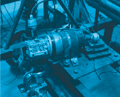
Figure 2 Experimental platform
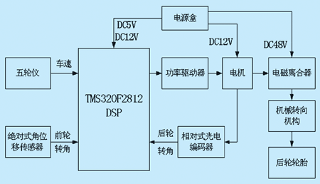
Figure 3 Block diagram
4 Control system hardware design and simulation
According to the control strategy designed above, the ECU unit collects the front wheel angle signal, rear wheel angle signal, and wheel speed signal and outputs the driving voltage of the motor through the CPU operation to realize the automatic steering of the rear wheel. This article uses C language to compile the program to realize the designed control algorithm, and complete the hardware-in-the-loop simulation debugging under CCS (Code Compose Studio) environment when the simulator is connected. CCS2000 is a set of Windows-based DSP integrated development environment for TI's TMS320C2000 series DSP, and it is also the best DSP development software at present. In the CCS environment, program development, debugging, compilation, linking, support for assembly and C / C ++ for software development, powerful debugging tools such as breakpoints, probes, profiling, and graphic display, etc., and finally output object files Burning.
4.1 Front wheel rotation angle signal collection The front wheel rotation angle is obtained by an absolute angular displacement sensor. The output voltage is linearly proportional to the front wheel rotation angle, and the range is 0 ~ 12V. This article uses the ADCHA0 pin of the CS4U9806 board to collect and integrate the sampling peripheral circuit DSP chip. The single-channel sampling time of this board is 200nS, and the input signal range can be selected through jumpers -5 ~ + 5V, 0 ~ 10V, 0 ~ 20V, and the default is-5 ~ + 5V. Due to the limited range of front wheel rotation angle, the jumper is selected from 0 to 10V, and the sampling frequency is set to 96HZ. Part of the program design process is as follows:
AdcRegs.ADCMAXCONV.all = 0x0002;
// Set the maximum conversion channel register to 2; AdcRegs.ADCCHSELSEQ1.bit.CONV00 = 0x0;
// Set the ADCHAO channel to sample continuously 3 times;
AdcRegs.ADCCHSELSEQ1.bit.CONV01 = 0x0;
AdcRegs.ADCCHSELSEQ1.bit.CONV02 = 0x0;
EvaRegs.T2CMPR = 0x0080;
// Set the compare register of timer 2;
EvaRegs.T2PR = 0xFFFF;
// Set the period register of timer 2;
EvaRegs.GPTCONA.bit.T2TOADC = 3;
// Enable the comparison interrupt to start the sampling module;
EvaRegs.T2CON.all = 0x1442;
// Enable the comparison unit, the sampling frequency is 96HZ;
interrupt void adc_isr (void)
// Sample interrupt service subroutine;
{voltf0 = AdcRegs.ADCRESULT0 / 16;
// Average the three consecutive samples to improve accuracy;
voltf1 = AdcRegs.ADCRESULT1 / 16;
voltf2 = AdcRegs.ADCRESULT2 / 16;
averagef = (voltf0 + voltf1 + voltf2) /3.0;
deltaf = (averagef-2970.0) * 3.2133 / (4096-2970.0);} // Calculate the front wheel angle and take radians; 4.2 Rear wheel angle signal acquisition The rear wheel angle signal is obtained by a high-precision incremental photoelectric encoder. It turns the rotation angle of the worm into corresponding up and down counting pulses according to the direction of rotation, and generates 2048 pulses per revolution, the output is a clock signal and a direction signal. This article uses the DICH0 (CAP2) pin to capture the clock signal, and the input pin DICH19 (GPIOF12) to obtain the direction signal. The design of the switch input circuit with optocoupler is shown in Fig. 4. The capture unit circuit is integrated inside the DSP chip.
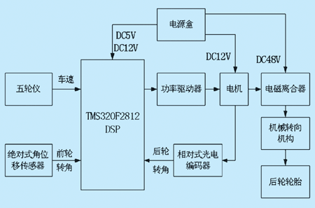
Figure 4 Block diagram of the input circuit
Part of the program design process is as follows:
EvaRegs.CAPFIFO.all = 0x0400;
// Set the initial value of the capture FIFO status register;
EvaRegs.CAPCON.bit.CAPQEPN = 0x1;
// enable capture unit 2;
EvaRegs.CAPCON.bit.CAP12TSEL = 1;
// Select Timer 1 as the reference;
EvaRegs.CAPCON.bit.CAP2EDGE = 0x1;
// Detect rising edge is valid;
EvaRegs.T1CMPR = 0x0080;
// Set timer 1 for capture unit 2;
EvaRegs.T1PR = 0xFFFF;
EvaRegs.T1CON.all = 0x1042;
interrupt void cap2_int (void)
// capture interrupt service subroutine;
{if (GpioDataRegs.GPFDAT.bit.GPIOF12 == 1) PosiTIvePulsecount ++;
else NegativePulsecount ++;
deltar = (PositivePulsecount-NegativePulsecount) * pi / 1024.0;
}
// According to the I / O pin to calculate the rear wheel angle, take the radian;
4.3 The basic idea of ​​algorithm design and D / A output algorithm is: when 4WS starts, input a front wheel rotation angle, and through yaw rate feedback, compare it with the speed-dependent ideal yaw rate steady-state response gain G0, and then The controller G1 controls the rear wheel angle to realize four-wheel steering, and outputs the center-of-mass lateral angle, yaw rate, and lateral acceleration for monitoring. The control block diagram is shown in Figure 5. The driving voltage of the motor is generated by the PWM comparison register of the DSP, which is output through the D / A conversion circuit. This text adopts the timer 4 to produce PWM, is exported by DA4 pin, the D / A conversion circuit of one-stage amplification is shown as in Fig. 6.
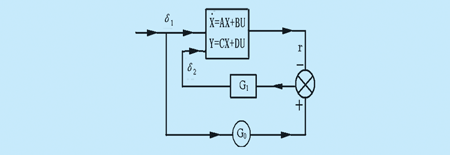
Figure 5 Control block diagram

Figure 6 D / A conversion circuit
Part of the program design process is as follows:
EvbRegs.T4PR = 0x3FF;
// Set the period register of timer 2;
EvbRegs.T4CMPR = 0x0080;
// Set the initial value of timer 4 compare register;
EvbRegs.T4CON.all = 0x1042;
// enable comparison unit;
EvbRegs.GPTCONB.bit.TCOMPOE = 1;
// PWM output driving timer 4;
EvbRegs.GPTCONB.bit.T4PIN = 1;
// The comparison output of timer 4 is active low;
y0 [0] = c [0] [0] * x0 [0] + c [0] [1] * x0 [1] + d [0] [0] * u [0] + d [0] [1 ] * u [1]; // The side angle of the centroid of the output volume;
y0 [1] = c [1] [0] * x0 [0] + c [1] [1] * x0 [1] + d [1] [0] * u [0] + d [1] [1 ] * u [1]; // output yaw rate;
y0 [2] = c [2] [0] * x0 [0] + c [2] [1] * x0 [1] + d [2] [0] * u [0] + d [2] [1 ] * u [1]; // lateral acceleration of output;
Dutycycle = volt_out / 10.0 * 1024;
// Calculate the duty cycle;
EvbRegs.T4CMPR = Dutycycle;
// reload timer 4 period register;
5 Conclusion This paper uses the control algorithm designed above to carry out TMS320F2812 DSP hardware-in-the-loop simulation of the 4WS vehicle. The vehicle parameters are selected as: m = 1740kg; I = 3214kg.m2; a = 1.058m; b = 1.756m; K1 = 29000N / rad; K2 = 60000N / rad; At the same time, for the sake of simplicity, the intercepting speed u = 30m / s, the result is shown in FIG. 7, the result shows that the 4WS vehicle with yaw rate tracking control has a horizontal center of mass during the steering control in the high-speed range The slew rate, yaw angle and lateral acceleration response can maintain better dynamic and steady-state performance than two-wheel steering. At the same time, CCS2000 is used for debugging and development, with a short period and low cost. Therefore, the DSP-based hardware control system has broad prospects in the field of industrial control and automotive control.
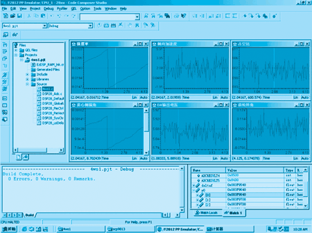
Figure 7 Simulation results
Cummins 0-20KW Diesel Generator
Cummins 0-20Kw Diesel Generator,Cummins Portable Power Generator,Cummins Open Type Power Generator,Cummins Container Power Generator
Shanghai Kosta Electric Co., Ltd. , https://www.ksdpower.com